Issue:
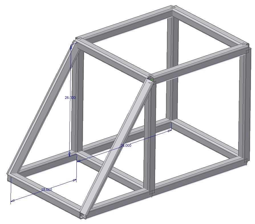
You want to add frame members at an odd angle, but do not know the angle at which they are to be added. Or when you select the edges, the members come in at an odd angle of orientation as shown in this image where the diagonals are pitched out. (you can click the image to see a larger version).
 |
| from: http://forums.autodesk.com/t5/Autodesk-Inventor/Frame-Generator-Bug/m-p/2936194 |
Solution:
Frame Generator follows two methods to define the initial orientation of a a frame member. For the first member in a selection the member is aligned to adjacent to the coordinate system. Then the rest of the selection set is aligned based off of the orientation of the first selection.


Warning:
You should be aware that if you change the skeletal model of the frame, then the orientation of the frame members who's orientation is set in the manner described in this tip, will be static and will not update. For instance, if I were to update the frame pictured above, by making it longer, the angle of the diagonal member will change. But the orientation of the cross members will remain as they are, requiring them to be updated manually. Just be aware of this so that is doesn't lead to costly errors.2013 Update:
Inventor 2013 offers a solution to this problem by allowing you to specify an alignment reference when placing the member via a new option.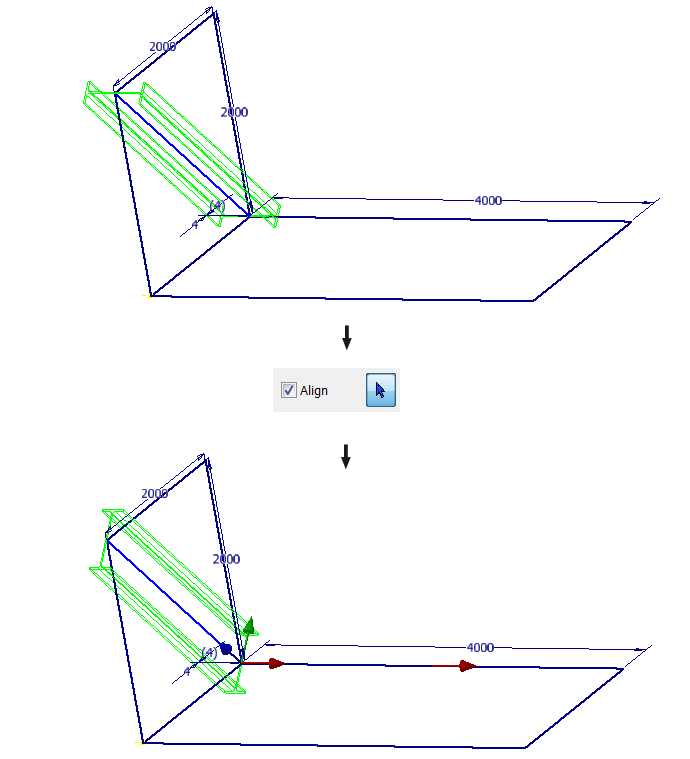 |
| Click to enlarge |
http://wikihelp.autodesk.com/Inventor/enu/2013/Help/0000-What_s_N0/0001-What_s_N1/0053-Assembly53/0056-Alignmen56