Thursday, March 31, 2011

Autodesk's New Certified Hardware Tool

Are you trying to figure out what graphics hardware to purchase to run your Autodesk products? 

Check out Autodesk's new Certified Hardware search tool. You can now search multiple products (Inventor and AutoCAD for instance) at once to find the best choice of hardware and drivers for the combination of Autodesk software you are running.


Also check out the Frequently Asked Questions for Inventor Hardware Certification page.
 

Sketch Constraints and the Eyeballing Game (slightly Inventor related fun)

If you've used Inventor for any length of time you've probably started to develop a "good eye" for sketching geometry at a relative proportion or scale. Sometimes when I apply dimensions to my sketch, I impress myself by just how accurately I've managed to get the sketch by just "eye-balling" it. Other times I'm not even close, though. Often times I purposely sketch things off center or skewed in one way or another, so that it is obvious to me what dimensions or sketch constraints I need to apply.

If you're a new Inventor user you might be employing the "eye-balling" approach inadvertently when you leave your sketches under constrained and/or under dimensioned. Of course this is not a good way to create sketches in Inventor (see: Inventor 101: Simple Fully Constrained Sketches), and you should (almost) always strive for a fully dimensioned and constrained sketch.

With these things in mind, I thought I'd share a link that provides a fun way to practice your "eye-balling" skills, and will likely make you more appreciative of your Inventor sketch constraints and dimensions.

The Eyeballing Game from woodgears.ca, prompts you to adjust a set of geometry for a given condition. For instance here the goal is to drag the lower left corner to make a parallelogram. The blue lines show my attempt, the green shows the correct position:


In Inventor I'd simply place parallel constraints to achieve this:


 Here was my attempt at setting a point equidistant to the edges of the triangle:

In Inventor I'd create a construction circle and then apply tangent constraints:


Here is my attempt at bisecting an angle:


In Inventor I'd add a symmetric constraint (or add angle dimensions):


Have a go at the The Eyeballing Game and you'll likely come away with an higher appreciation for sketch constraints and dimensions.

http://woodgears.ca/eyeball/index.html

Monday, March 28, 2011

Quick Hole Patterns with the Polygon Sketch Tool

Here's a quick tip for creating a hole pattern using the Polygon sketch tool.


The goal is to add a centered hole pattern with 8 holes:


To start I'll create a sketch on the part face to be drilled, then I'll use the Polygon tool found on the Draw panel of the Sketch tab. I'll set the number of sides to 8 and then place the polygon in an approximate location:


Next I'll constrain the polygon into place using dimensions and constraints. I'll place a horizontal or vertical constraint on one edge of the polygon to lock in the orientation:


Next I'll select all of the edges. I typically do this by creating a crossing window selection from left to right. Then I'll hold down the CTRL key and deselect the center point of the polygon since no hole is required there:


Then I'll use the Center Point tool found on the Format panel of the Sketch tab to toggle the points from a simple endpoint to center points:


Then I'll finish the sketch and click the Hole tool button. Because I have only one visible, unconsumed sketch present, Inventor automatically chooses the From Sketch placement method. And because my sketch contains 8 center points, the Hole tool automatically selects them:


And here's the result:


One reason not to use this method is that you can't take advantage of the Associative Pattern option in the assembly that allows you to place assembly components by referencing a part level feature pattern. So a little forethought in how the part will be used in the assembly will help. 

With that in mind I find myself using this trick a lot. Many times I'll do this with corner hole rectangular patterns created by offsetting a plate edge:


Wednesday, March 23, 2011

Detailing Frame Generator Weldment Members Individually While Still Maintaining Assembly Features

Issue:
You have a Weldment Frame Assembly with assembly level features (cuts or holes in the parts made in the assembly rather than the parts themselves) and you want to detail each member of the frame individually and have it show the various assembly level features you've created. The problem is, the features do not exist in the part files. Is there a solution to this?

Solution:
There are actually a couple of solutions to this. The first one is the proper way to get the results you're after, but it's often overlooked. Even in a standard assembly weldment, many Inventor users overlook this functionality, and I’ve seen others go so far as to say it can’t be done (it can, of course). But when you add a fame generator sub-assembly into the mix,  fewer Inventor users connect the dots to get this all to come together. So I’ll go through the correct process here, but I'll also offer a workaround in case you're reading this after having already started out on a different path.

First off let’s make sure we understand how to detail members of a standard weldment assembly individually so that the preparation cuts and holes created in the assembly can be detailed too.

Here I have a weldment assembly made of two instances of the same block, Block100:


Because these blocks are the same stock part, if I need to create the hole in them I need to do it at the assembly level. If I tried creating this hole at the part level in each instance, I would end up with 2 holes in both instances (as well as all of the instances of this part I used in every other assembly). So this is a bad idea. Another approach is to save off a copy and start making “renditions” of this part (also generally a bad idea if it’s intended to be the same stock part number). 

So, to detail each part individually using the proper technique, I first create the hole as a weldment preparation feature. Then I create a drawing view of the weldment assembly, and go to the Model State tab of the weldment view and choose which member to detail. This is kind of like using a Level of Detail, but it's all set up for you automatically as a function of the weldment tools:


When you choose Block100:1 only that part is included in the view. Here is a drawing of the same weldment assembly file. Each view uses a different model state of the weldment preparations. You'll notice the browser displays which part(s) is shown:

Click to Enlarge
So that's the basics of detailing parts individually from a weldment assembly There is an entire chapter dedicated to Weldments in the Mastering Inventor books (hint, hint). It's because of this added ability to filter for just one part at a time, that I recommend converting Frame Generator sub-assemblies to weldments even if they are not truly going to be welded. Then you can create your assembly features in the Preparations folder and take advantage of the weldment drawing tools. But you have to do this in the Frame Generator sub-assembly NOT the top level assembly. To understand the issue more completely, let's first take a look at the anatomy of a Frame Generator assembly. 

When you created your first frame member you were prompted for a New Frame File Name and a New Skeleton File Name:


Here is a simple Frame browser structure:


CW-0323-01.iam = Top Level Assembly
Frame_Skeleton_CW-0323-01 = The user created part the frame is based on
Sub_CW-0323-01 = The subassembly that Inventor creates with Frame Generator. This is where the frame members reside (Sub_CW-0323-01.iam).
Frame Reference Model = The reference part that Inventor creates with the Frame Generator. This is where the copied reference edges used in the member placement reside (CW-0323-01_Skeleton.ipt)


Here is the same simple frame with assembly features created in the top level assembly (in this case it's been converted to a weldment).


This is not the preferred place to create these features, because we can't detail the individual members with the assembly level cut features if they are placed in the top level. Instead, assembly level features should be created at the frame subassembly level. 


In this next image the frame sub-assembly has been edited, converted to a weldment, and then assembly level features were created. The results are the same as before, but the features reside in the sub-assembly, which is required in order to use the Model State tab in the drawing views correctly.


When the features are created in the sub-assembly, you can simply create a detail drawing of the frame subassembly weldment (not the top level assembly) and then use the Model State tab to set the weldment Preparation option to look at each member of the weldment individually, just as you can do with any weldment assembly. Here is the frame sub-assembly in a drawing:


Here the Model State tab is being used to filter for just one part is to be used in the drawing view:


Here the individual frame member is being detailed, showing the preparation cut on the left. You'll notice the machining features (the circular cut and the chamfer of its edges) are not included, because those features are post weld features and are not part of the piece parts, but instead applied to the weldment as a whole.


That's all there is to it. As long as you convert the frame sub-assembly to a weldment, and then place your assembly features in that sub-assembly (and not the top level assembly), this works fine.


The Work Around
But what if you've already created your features in the top level assembly? 

If you've already created the features at the top level assembly, rather than the frame sub-assembly, you really should just take the time to recreate those features at the right assembly level. But if that would entail a great deal of work, you can use Level Of Details to suppress all of the parts you don't want in a view and then detail it using the Level of Detail in the view. (as with any workaround you might find flaws in it).

To do this first set the selection filter to Select Part Priority, so that you can reach down into the frame sub-assembly and select individual parts:


Next create a new Level of Detail:


 And suppress the parts you don't want to see:


Then suppress the welds if needed:


 Create a drawing view of the top level assembly, and use the Level of Detail:


There you have it. It would be ideal if you could just select the assembly features and demote them into the frame sub-assembly. But currently you can't do that.

As mentioned before, I recommend converting Frame Generator sub-assemblies to weldments even if they are not truly going to be welded. Then you can create your assembly features in the Preparations folder and take advantage of the weldment drawing tools.

Suggested Improvement (hint for Autodesk)

I think that this process could easily be improved by Autodesk if they were to make all Frame Generator sub-assembly files automatically have the same ability to "filter" for a single part file in the drawing view Model State tab, that weldments currently have.

If you'd like to suggest this to Autodesk also  you can use this form:
Feature Request For Inventor

Find Interference and Add Tolerance To Mating Parts

Issue:
 You'd like to identify an interference between two parts. In addition, once identified you'd like to subtract the one part from the other and then add some tolerance to the subtracted feature.

Solution:

You can use the Analyze Interference tool to find interference.


When you analyze interference, the tool seems to require you to define 2 selection sets, but you can create just one.  If you add components to both sets, all of the components in selection set 1 are checked against all of the components in selection set 2.  But if you do this Inventor will not report any interference between components within the same set. This can actually be very helpful when you want to ignore known interferences (such as press fits), but check those components against others.

With all of that in mind, I can tell you that I almost never define a set 2, instead I just add everything to set 1 and then click OK. With just one selection set, Inventor checks for interference among all of the selected components.


Once identified edit the part to subtract from, while in the assembly. Then use the Copy Object tool to select the interfering part and set the Create New option to be a surface.  Note the Associative checkbox indicating that the resulting Copy Object surface will be Adaptive. Therefore, changes to the copied part will update if/when the part updates.


Here you can see the results of the Copy Object.


Next you can use the Sculpt tool to convert the surface to a new solid.


Here you can see the results of the Sculpt tool.


Next use the Combine tool to subtract one solid from the other.


And finally, use the Thicken/Offset tool to subtract-offset the resulting feature faces with a tolerance as required.


Keep in mind that it is always a good idea to toggle the adaptive status of a part to be off once that part is at a "stable" design point. If you need to make changes that involve the adaptive feature again, you can toggle the adaptive option back on.


Additionally, here is a Youtube video I made on this subject a while back that shows a shaft being subtracted from a foam insert:


And here is a Youtube video from Rusty Belcher at Imaginit that covers this subject very well also:

Plastic Part Quote From Protomold.com Using My Inventor Parts


I recently sent a couple of small part files out for quote to several injection molding companies. Most of these were local companies or companies we'd done business with in the past. But for the sake of due diligence (and curiosity) I sent these parts to Protomold.com as well. I thought I'd take a moment and share some of the feedback I received from them. 

First off, I should state that the Protomold price and lead time were very competitive with most of the other shops we obtained quotes from.

One of things that was nice about the Protomold quote is that it was provided online and was adjustable in the Specifications area, which allowed me to change various options such as Finish, Quantity, Material, etc. and see the price per piece update based on the changes. This was particularly useful on this project, as part of the design decision was deciding if it was cost effective to have these parts injection molded (versus buying and machining off the shelf components). 

(some information has been "black blocked" for privacy)


The next part of the quote is the Review Issues section. For this particular part Protomold found 7 issues with the STEP file I submitted. These issues were categorized, and in my case I had 2 issues that "Required Changes". Both of these were due to my part file containing incorrect drafts on the faces of holes that I added or changed at the last minute, but forgot to adjust the draft on.  I had 3 "Moldability Advisories" which included suggestions about the texture of the finish, etc. 


These issues could have been caught in Inventor had I remembered to use the Analysis tools again after making changes to the model. I used these to verify the changes I made after the Protomold pointed them out (better late than never, huh?).


There were also 2 "Other Info" issues,  informing me of minor changes that would be made to the finished product, due to the milling process. In my case these involved sharp edges in my model that would actually end up being small radii in the real part, and were not of concern.


Of course many of the other shops I spoke with provided feedback on the models I submitted as well. As is common, they suggested minor changes to the parts to allow them to manufacture them in a more cost effective way  via email or over the phone.  But being a CAD person, the Protomold feedback was particularly interesting. 


So the next time you're requesting quotes for injection molded parts, you might submit it to Protomold.com as well, for some very helpful feedback and a competitive quote.
 

Monday, March 21, 2011

Part Modeling Practice Drawings for Inventor


Are you looking for a few dimensioned drawings to practice your Inventor modeling with? I've put together 24 sheets of detailed part drawings for practice in a PDF.


You can download this file by clicking the Download button on the viewer control frame, or find it on the Tutorials page. I hope you find these helpful.


Alternative DropBox download link:


Youtube.com video versions of these files by Nivesh and Nisheeth:
http://www.youtube.com/watch?v=FXyopiUEp40&feature=share&list=PLKWX3xUP3pPogJ-snxl4NP18CEi-I82dU

Update:
In addition to these drawings you can find several "projects" at this link:


Inventor Wizards
An entire page devoted to model engine plans from Inventor Wizards:
http://www.inventorwizard.be/blueprints/index.html


Thursday, March 17, 2011

Understanding Autodesk Inventor Frame Generator, Bill Of Materials and Part Numbers


Issue:
With the help of the Frame Generator you've used Inventor to successfully design a frame. The problem is in the way that Inventor creates a file for each member, and automatically sets the file name to the Part Number field. You've tried renaming part files but this seems to break more than it fixes. Isn't there anyway to get Frame Generator to cooperate and provide a Part's List that can be used for production?

Solution:
This is a bit of a process, but once you've done it a few times you'll get the hang of it. Also, keep in mind that you can set up a frame assembly template to have much of this done for you automatically in the future.

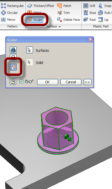
First off, for the most part you can forget about file names when using Frame Generator (FG) , and just let FG name the files as it sees fit. You do this by un-checking the File Naming checkbox as shown:


Typically the only FG files I set the name for are the frame sub assembly and the skeleton part file. Example:
UX950.iam = the container subassembly that all of the frame members will be placed in
UX950_ skeleton.ipt = the reference file that geometry is copied to. For instance when you select an edge to place a frame member, that edge is copied into the skeleton part file.

Here is a simple example I'll use to explain this better. As you can imagine there are many members of the frame that are identical, and ideally we'd like to have those members share a common part number.


Here some identical frame members (the stair treads) are shown in red.

Here the railing members are color coded to show the common members.


The first thing to do is edit the Bill of Material (BOM). Go to the Assembly tab and click the Bill of Materials button to bring up the BOM editor. 


Next, let's talk a bit about the quantity columns in Inventor.
Inventor has 4 of them, Base QTY, Item QTY, Unit QTY and QTY. You can use the Choose Column button to add them to the BOM for review (this doesn't impact the parts list on the drawing).

Base QTY = length of the part (reads the G_L iProperty from the part file). Can be changed in the BOM editor.
Unit QTY= the same as Base QTY, is read only and can't be changed in the BOM editor.
Item QTY = counts the number of parts in the assembly with the same part number
QTY = Base QTY x Item QTY


To add these columns to the BOM editor you can drag and drop columns to the BOM grid. Drop the item on the header row to add. Drop it anywhere you see the black X to remove it.


Okay, let's get started. I use the Add Custom iProperty Columns button to create custom columns in order to adjust the BOM to my needs. These custom iProperties will be pushed down from the assembly and written to the part files.


I'll add two new iProperties, one called Job Number and the other Mark Number.


Once added to the BOM grid you can enter a value for the Job Number and then use the Fill function to copy it to all of the cells below it. This writes the Job Number to each file shown in the BOM.


Next I'll use the Create Expression button to create an expression in the Part Number cell of the first member in the frame.  


I like to create a temporary expression using the Job Number, Stock Number, G_L and Mark Number properties. Even though the Mark Number is currently empty.


I then use the Fill function to copy the expression to all of the cells below it, just as I did when adding the Job Number. It is at this point, that I like to check and make sure the reference part that I used to select edges from for the frame is set to be Reference, so that it does not show up in the structured BOM or impact the mass properties of the assembly.


Once that is done I switch from the Model Data tab to the Structured tab and enable it if needed.


You'll notice that in the structured tab the parts are grouped by part number. This is controlled by the Part Number Merge Settings. I want this option Enabled.


Because the frame members are being merged by Part Number, and the Part Number consists of the Project Number, Stock Number and Length (G_L), I'm able to select the members with the same length as a single line item, and see them highlighted in the model. Here the tread channels of the ladder are selected:


Since all of these are the same, with none of them being mirrored or having a different hole configuration, etc. I can apply the same Mark Number to them. Adding the mark# to the Mark Number cell, automatically adds it to the Part Number, because of the expression in the Part Number cell.


I then do this for each of the common member groups as needed.
But then how do we separate out the members that are the same stock profile and the same length, but are right and left mirrors such as the sides of the platform shown?


To do this select the row, and then click the Show button at the top of the BOM editor.


This will expand the group and allow you to add Mark Numbers to each row.


For some reason, the members aren't highlighted on screen when doing this. So if the mark# needs to be something like P1L (for left) and P1R (for right) I'll typically just mark them both as P1 at first, and then flip back to the Model Data tab and determine which is the right and which is the left, and then adjust the mark numbers as needed.


Once the mark #'s are set, use the Clear button at the top of the BOM editor to collapse the group.


Okay, so once I have the mark numbers set for all of the members, I'll then adjust the part number expression to use only the Project# and Mark#.


Here the top cell has been adjusted and I used a dash to combine the project# and the mark#.


Then I use the fill function to copy the expression to all of the other part number cells.


Then I'll click on the Part Number header in the grid to sort by part number. You can also use the Sort button at the top of the BOM editor dialog box.


Once sorted, I'll use the Renumber button to update the Item numbers.


And then I'll add expressions to the Description field to adjust them as needed.


Here is an idea of what the BOM would look like when done. Notice how the quantity columns reflect different values now. The icons on the far left with the different length bars and an arrow, indicate the merged rows.


And finally, I'll use a balloon style that calls the Part Number and the Item QTY properties as shown:
Click to Enlarge