Friday, May 27, 2011

Using AutoCAD Sheet Set Manager With Inventor Drawing Files

Issue:
You create drawing packages (sheet sets) for your engineering projects and have tried placing all of the drawings into one Inventor drawing file. The problem with this is that opening and editing this file gets slower and slower and slower as you continue working through the project, because Inventor must calculate all of the views on all of these sheets every time, even for something as simple as a text note change. Worse still, is that you've lost work when that one drawing file became corrupt and all of the sheets within it could not be accessed. Surely there is a better way, right?


Solution:
I always discourage the practice of creating Inventor drawing files with a lot of sheets in them, for the reasons mentioned above. But since Autodesk has been slow to address the need for a sheet set manager in Inventor, I've looked into using the sheet set manager in AutoCAD to manage Inventor DWG files. Note, that you can't use the AutoCAD sheet manager for Inventor IDW's unless you convert your IDW's to DWGs.

So if you create your Inventor drawings as Inventor DWG files with the idea of one part file = one drawing file, and then create general assembly files and additional details sheets as needed, you can use AutoCAD to package those files together for ease of management.

To start, Open AutoCAD and make sure you have at least one file open. This can be any file including a new blank file you don't intend to save. But you must have at least one file open to use the Sheet Set Manager.

Click the Sheet Set Manager button as shown:


 With the Sheet Set Manager panel open, click the drop down as shown, and choose New Sheet Set:


 Next select the Existing Drawings option and click Next:


 You can then specify the details of the sheet set as shown in this example:
 

In the Sheet Set Properties dialog you can add additional information and create custom properties:


Here a custom property named Vendor Code has been added:


 Next you'll choose the sheets (or layouts) to add. In this example I've deselected some folders that I don't want the Sheet Set Manager to look into. Other folders that are included don't contain Inventor DWG files yet, but I've included them anyway.


Clicking the Import Options button allows you to set some naming and structure options:


The Sheet Set Manager returns a list of the files it found in the locations specified. In this case I'd only finished detailing four of the components of my design, so only four DWG files existed, and they are listed in the Confirm dialog:


Once created, the sheet set (Job 140-004) is listed in the Sheet Set Manager panel, with the drawings it includes listed below:

Double clicking any of the nodes in the sheet set list opens the drawing. Keep in mind that because these files were created in Inventor, the Inventor data is protected and can edited in Inventor (although you can add AutoCAD objects to the file in AutoCAD).

For more about how AutoCAD and Inventor interact with Inventor DWG files you can search for the term DWG TrueConnect.

Here are a couple of links to get you started:
An Autodesk University class on DWG TrueConnect 
A blog entry from Hagerman & Company answering questions about DWG TrueConnect


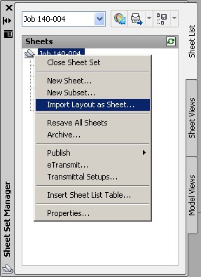
If you right-click on the top node of the sheet set, you'll see a list of options you have for working with the sheet set:


To add an new Inventor DWG to the sheet set you can right-click on the top node of the set and choose Import Layout as Sheet, and then simply browse and select an existing Inventor DWG file.


Once a new sheet has been added, you can right-click on it to Rename & Renumber it as needed. Reordering sheets is as simple as dragging them up or down in the list.


 Of course there are a number of options available for publishing the sheet set as well.
 

A proper sheet set manager native to Inventor has been requested for a number of years. Although using AutoCAD for this might work for you if you use Inventor DWG files, users who prefer IDW files (for the smaller file sizes) still don't have a good way of doing this. If you think Autodesk needs to include a sheet set manage in Inventor use this Autodesk Feedback link to tell them about it.The more requests they get, the more likely they are to see the need for this feature, so do your part and let them know what you think.

More about working with Sheet Sets in AuotCAD:

Thursday, May 26, 2011

Using Isolate Before Creating Assembly Feature Cutouts Saves Time and Effort

Issue:
When you create assembly level features to make cutouts in stock parts, you often find yourself having to remove participants from the features. Because the components that you are removing from the assembly feature participation are complex, Inventor takes a long time to cut them when the assembly feature is initially created and then takes a long time to calculate when removing them from the feature participation as well. You'd like to know if there's a better way to handle this, so that you don't have to wait on Inventor twice to  cut, and then uncut complex parts that you don't want to cut in the first place.

Solution:
If you isolate just the component (or components) to be involved in the assembly level cut feature before creating the feature, Inventor will only consider it in the feature participation. This will keep the calculation times short and eliminate the need to remove components from the feature participation that you didn't want to include to start with.

Let's review the standard procedure for creating assembly features first, and then we'll have a look using Isolate to make this more efficient.


Here I have an enclosure modeled with a circuit card inserted into it. The connectors and switch used on the circuit card are currently sticking through and interfering with the top plate of the enclosure. Because I use the same top plate for many enclosures, I stock it as a standard part, with no cutouts included. Then I create cutouts in this stock part as needed for specific designs. I want these cutouts to exist at the assembly level only, so they don't impact my standard top plate, so I use an assembly level feature cutout rather than creating the cutout in the actual part file.

Here you can clearly see the circuit card and switch part files that I want to create cutouts for. Note that the circuit card is really an assembly of many small complex parts, but because it is provided to me as a single part number it is contained as a single part file here.


The first thing I'll do is create a sketch on the top plate. Again, it's important that I do this from the assembly level and not at the part level. So in the assembly, I go to the Model tab and click Create 2D Sketch and then select the face of the top plate.


I'll then use the Project Geometry tool to pull in reference edges of the circuit card connectors and the switch, in order to precisely locate and size my cutouts.


Here the sketch has been completed. Notice where the sketch resides in the assembly browser.


I'll use the Extrude tool to make the cutout feature from the sketch. Recall that assembly level features can only remove material, therefore the Join, Intersect, and New Solid options are not available. 

In this case I'm using the All extents option. Doing so allows me to change the thickness of the top plate later if needed, without having to come back and adjust this extrude feature. Keep in mind that even if I set the extents to a distance equal to the top plate thickness, the circuit card and switch would get cut by that much.

The assembly feature is created as Extrusion 1 and placed in the Assembly browser, as shown. You'll notice there are three participants involved in the Extrusion 1 cut and listed in the browser. It took a bit of time to calculate this cut because the circuit card file (01-0322-06 Rev 1) has a lot of complex geometry.


Here the top plate has been removed so you can see that Extrusion 1 has cut through the circuit card and switch as well as the top plate.


To remedy this, I'll select the parts I don't want to be included in the cutout feature and then right-click and choose Remove Participants, as shown:


This removes the other files from the assembly level feature so that only the top plate is being cut. Removing the participants takes a while to calculate again because of the complex geometry involved in the circuit card model. But in the end I get the result I'm after: cutouts in the top plate, that only exist in the assembly file.


A better way, using the Isolate option

So let's look at a better way. I'll step back in time to the point at which I'd just finished creating my sketch at the assembly level. So now I'm ready to create the cutout. But this time I will select only the part (or parts) that I want to create the cutout in, and then right-click and choose Isolate. In this case I only want the cutout in the top plate part.


The result of using Isolate is that the visibility setting of all of the parts not selected (in this case, everything but the top plate) is toggled off.
Now I can create the Extrude cut, this time only involving the part I intend to be cut and no other parts.

The browser shows that Extrusion 1 is only cutting the part named 10-0312-12 Rev 1 (the top plate). So there is no need to remove any unwanted participants from this feature, and no need to wait for Inventor to calculate the inclusion of parts I don't intend to cut.


To turn all of the other components back on, I'll simply right-click and choose Undo Isolate. This will toggle the visibility setting of all the components that are off, back on.


One thing to know about using Isolate and Undo Isolate is that if you manually toggle the visibility of a component after you use Isolate, but before you use Undo Isolate, you can upset the Isolate selection set, and will likely have to manually toggle the rest of the components back on. So don't mess with the visibility of components during the use of Isolate.


Once Undo Isolate is used I'm done:

If you happen to forget to include a component in your selection before isolating, and then realize this after the the assembly feature has been created, you can just right-click the feature (Extrusion 1 in this case) and choose Add Participant. Then just click the component to add in the browser and it will be listed under the assembly feature, and any material in that component that intersects the cut feature will be removed.


So don't forget to use Isolate to narrow the scope of your assembly level features. 

Friday, May 20, 2011

Use iLogic to Change Sheet Orientation from Landscape to Portrait


Issue:
You have some iLogic code to help you setup your drawing sheets. But you need one last bit of code to change the orientation of the sheet (see this link from Jonathan Landeros for a great example of using iLogic to configure title block and borders).


Solution:
You can use Page Orientation Type Enumeration to handle this. Here are two example rules that change the orientation of the active sheet. One prompts the user to choose the orientation, and the other asks the user if they want to flip the orientation. You can use the orientation enumeration portions of these rules in your own iLogic code to flip the sheet orientation as you see fit.

This first rule prompts the user to choose the orientation.


'-----------------Start of iLogic Code---------------------------------------
'PageOrientationTypeEnum Enumeration
kLandscapePageOrientation = 10242
kPortraitPageOrientation = 10243

'prompt user to select orientation
booleanParam = InputRadioBox("Select Sheet Orientation", "Landscape", "Portrait", True, Title := "iLogic Sheet Orientation")

'set orientation based on user input
If booleanParam = True then
ThisApplication.ActiveDocument.ActiveSheet.Orientation  = kLandscapePageOrientation
Else
ThisApplication.ActiveDocument.ActiveSheet.Orientation  = kPortraitPageOrientation
End if

'zoom all
ThisApplication.ActiveView.Fit
'-----------------End of iLogic Code---------------------------------------


Here is a second rule that looks at the current orientation and then asks the user if they want to flip it.


'-----------------Start of iLogic Code---------------------------------------
'PageOrientationTypeEnum Enumeration
kLandscapePageOrientation = 10242
kPortraitPageOrientation = 10243

CurrentOrientation = ThisApplication.ActiveDocument.ActiveSheet.Orientation

'prompt user to select orientation
OientationQuestion  = MessageBox.Show("Do you want to Flip the Sheet Orientation?", "iLogic Flip Sheet",MessageBoxButtons.YesNo)

'set orientation based on user input
'if user chooses yes and current orientatation is Portrait
If OientationQuestion = vbYes and CurrentOrientation  = 10243 then
'flip to landscape
ThisApplication.ActiveDocument.ActiveSheet.Orientation  = kLandscapePageOrientation
'if user chooses yes and current orientatation is Landscape
Else if OientationQuestion = vbYes and CurrentOrientation  = 10242 then
'flip to portrait
ThisApplication.ActiveDocument.ActiveSheet.Orientation  = kPortraitPageOrientation
'dont flip
else if OientationQuestion = vbNo then
End if

'zoom all
ThisApplication.ActiveView.Fit
'-----------------End of iLogic Code---------------------------------------

Thursday, May 19, 2011

Use iLogic to Add and Use a Custom iProperty All in One Rule

Issue:
You want to have a rule that checks for a custom iProperty and then adds it if it is not already created. Then you'd like to use that custom iProperty in the rest of the rule.


Solution:
Here is a bit of code that uses Try/Catch to query the custom property set and add the custom properties to the file if they are not found. It then goes on to use an input radio box to prompt the user to choose between two possible options for the part finish. And then finally it sets the Finish and Finish Code custom iProperties based off of the user input.


' ---------------------start of iLogic code---------------------
'check for custom iprops and add them if not found
Dim propertyName1 As String = "Finish"
Dim propertyName2 As String = "FinishCode"

customPropertySet = ThisDoc.Document.PropertySets.Item _
("Inventor User Defined Properties")

Try
          prop = customPropertySet.Item(propertyName1)
          prop = customPropertySet.Item(propertyName2)
Catch
      ' Assume error means not found
            customPropertySet.Add("", propertyName1)
          customPropertySet.Add("", propertyName2)
End Try

'output the custom iproperties and update the file
RuleParametersOutput()
InventorVb.DocumentUpdate()

'prompt user for iProperty value
booleanParam1 = InputRadioBox("Select Finish", _
"Primed for Painting", "Bright Stainless Steel", True, Title := "iLogic Finish")

'set iproperties based upon user input
if booleanParam1 = True then
iProperties.Value("Custom", "Finish") = "Primed for Painting"
iProperties.Value("Custom", "FinishCode") = "600"
else
iProperties.Value("Custom", "Finish") = "Bright Stainless Steel"
iProperties.Value("Custom", "FinishCode") = "629"
end if

'update file
iLogicVb.UpdateWhenDone = True

' ---------------------end of iLogic code ---------------------

A big THANK YOU to Mike Deck of Autodesk for the Try/Catch example for creating a custom iProperty via iLogic.


Update:
Wednesday, August 01, 2012
I ran into an issue with combining more than one custom iProperty in the Try/Catch, and have found it better to keep them separate as I show in the example below.

This example also demonstrates how to add a Text, Date, Number, or Yes/No type custom iProperty.


' ---------------------start of iLogic code---------------------

Dim propertyName1 As String = "Paint Code"
Dim propertyName2 As String = "Size"
Dim propertyName3 As String = "Galvanized"
Dim propertyName4 As String = "Completion Date"

'define custom prp[erty collection
oCustomPropertySet = ThisDoc.Document.PropertySets.Item("Inventor User Defined Properties")

Try
'set property value
oProp = oCustomPropertySet.Item(propertyName1)
Catch
' Assume error means not found so create it
oCustomPropertySet.Add("", propertyName1)
End Try

Try
'look for property
oProp = oCustomPropertySet.Item(propertyName2)
Catch
' Assume error means not found so create it
oCustomPropertySet.Add("", propertyName2)
End Try

Try
'look for property
oProp = oCustomPropertySet.Item(propertyName3)
Catch
' Assume error means not found so create it
oCustomPropertySet.Add("", propertyName3)
End Try

Try
oProp = oCustomPropertySet.Item(propertyName4)
Catch
' Assume error means not found so create it
oCustomPropertySet.Add("", propertyName4)
End Try

Dim strPaintCode As String
Dim dblSize As Double
Dim blGalv As Boolean
Dim dtDate As Date

'get values from user
strPaintCode = InputBox("Enter the paint code.", "iLogic", "") 'no default value
dblSize = InputBox("Enter the size.", "iLogic", 100) 'set default to 100
blGalv = InputRadioBox("Is this thing galvanized?", "Yes", "No", True, "iLogic") 'default is True (yes)
dtDate = InputBox("When was this completed?", "iLogic", Now.ToString("MM/dd/yyyy")) 'set default to today's date

'set custom property values
iProperties.Value("Custom", "Paint Code") = strPaintCode
iProperties.Value("Custom", "Size") = dblSize
iProperties.Value("Custom", "Galvanized") = blGalv
iProperties.Value("Custom", "Completion Date") = dtDate

iLogicVb.UpdateWhenDone = True

' ---------------------end of iLogic code ---------------------


Update:
August 03, 2013
Here is another version that is a bit more tidy:


' - - - - - - - - start of iLogic code - - - - - - - -
Dim sProp1 As String = "Destination Code"
Dim sDestCode As String
  'define custom property collection
oCustomPropertySet = ThisDoc.Document.PropertySets.Item("Inventor User Defined Properties")

Try
            'get current custom property value
                sDestCode = iProperties.Value("Custom", sProp1)
            'get user input
                sDestCode = InputBox("Enter the Destination Code:", "iLogic", sDestCode )
            'set custom property value
                iProperties.Value("Custom", sProp1) = sDestCode
Catch
            ' Assume error means not found so create it
                oCustomPropertySet.Add("", sProp1)
            'get user input
                sDestCode = InputBox("Enter the Destination Code:", "iLogic", sDestCode )
            'set custom property values
                iProperties.Value("Custom", sProp1) = sDestCode
End Try

iLogicVb.UpdateWhenDone = True
' - - - - - - - - end of iLogic code - - - - - - - -