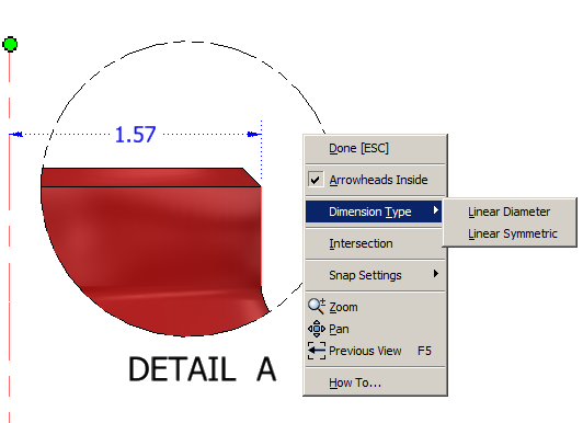
You need to place a foreshortened diameter dimension in a detail view, but can not find an edge to select that will give the correct results.
The dimension here shows the results you are trying to achieve:
Solution:
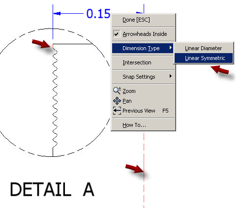
The first step to achieve these results is to place the center line. To do this you can use the Automated Centerlines tool: Right-click on the detail view and choose Automated Centerlines from the menu.

To add a diameter symbol for the Linear Symmetric style simply edit the dimension and use the Insert Symbol button to add the symbol:
You can then right-click on the center line and deselect the visibility option to hide the center line if needed. Note to get the center line back after you've hidden it, you can right click on the view and choose Show Hidden Annotations.
If you placed a Linear Diameter dimension you can right-click it and choose Options > Full Dimension Line to show the other end of the arrow, extended out to the actual diameter length, if needed.
Update 3-13-2013:
To do this for dimensions that are not diameters you can do something similar:
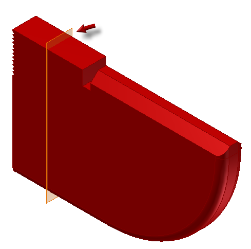
- First create a workplane in your model that is 1/2 the distance between the two features/edges you want to dimension. It needs to be1/2 the distance because we're going to trick Inventor by using a centerline created from this workplane. Here I've created a workplane bisecting two parallel planes:

- Next, create the detail view of the drawing and then expand the model for that view in the browser, and locate the workplane, then right-click on it and choose Include, this will bring in the workplane as a centerline:

- Next create a dimension between the edge and the workplane / center line, then right-click and choose Dimension Type > Linear Symmetric.

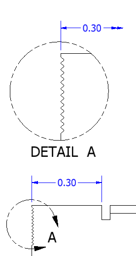
- Then right-click on the workplane / center line and choose Visibility.

- You should have the result you're looking for.


